Week 5: 3D Scanning and Printing
What should I do this week?
In this fifth week of Fab Academy, I need to design and 3D print an object that cannot be subractively manufactured, 3D scan an object and 3D print it & complete a group assignment to find the capabilities of the 3D printer. Further learnings from this week are listed below:
- Try out various types of 3D printers with different additive manufacturing technologies and try to push them to their limits.
- Document all my learnings and failures in layman language and try not to damage the machines
- Work as a group, to test various limitations of the machine like overhang, precision,
- Design and 3D print a novel product which fits all the assignment criterion
- 3D scan an object, prepare it for printing and make it happen
- Explain various additive manufacturing technologies
- Include original design files for 3D printing
- Make something interesting
The following are the softwares that I have used for learning various operations:
- Autodesk Fusion 360 : 3D Modelling, Assembly & Animation
- Cura : Slicing
- Artec Studio: 3D Scanning
Week 5: Action Plan
| |
|
|---|---|
| Wednesday | Prof. Neil's class on 3D Printing, Scanning, Materials & Designs |
| Thursday | Understanding the 3D Printer, Different types of additive manufacturing technologies |
| Friday | 3D Modelling & 3D Printing : Trial & Error |
| Saturday | 3D Printing |
| Sunday | 3D Printing |
| Monday | 3D Scanning |
| Tuesday | Printing the 3D Scanned Image, Various types of 3D Scanners |
Additive Manufacturing & Types of 3D Printers
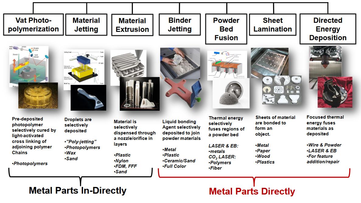
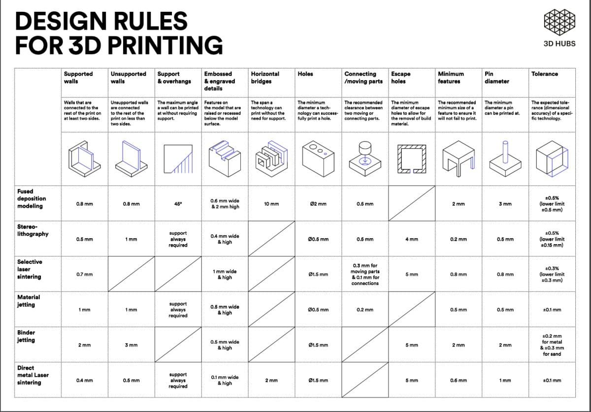
Since I am a mechanical engineer by education, I already had knowledge about various types of 3D printers and various technologies used. But, I like to explain it once again for the newbies that visited my page. The term “3D printing” is increasingly used as a synonym for additive manufacturing. However, “additive manufacturing” better reflects the professional manufacturing process that differs significantly from conventional, subtractive manufacturing methods. For example, instead of milling a workpiece from a solid block, additive manufacturing builds the part up layer by layer from material supplied as a fine powder. Various metals, plastics and composite materials can be used. Additive manufacturing is relevant in many areas and for numerous industries. Whether used for building visual and functional prototypes or small and medium series - and increasingly for series production. This method offers convincing advantages conventional methods cannot achieve. Product development and market entry can be significantly accelerated, agile product customization and functional integration can be achieved more quickly and at a lower cost. In this way, additive manufacturing gives large OEM manufacturers from a wide variety of industries the opportunity to differentiate themselves on the market in terms of customer benefits, cost reduction potential and sustainability targets. There are various types of additive manufacturing technologies:
| Type | Explanation |
| VAT Photopolymerisation | Vat polymerisation uses a vat of liquid photopolymer resin, out of which the model is constructed layer by layer. An ultraviolet (UV) light is used to cure or harden the resin where required, whilst a platform moves the object being made downwards after each new layer is cured. |
| Material Jetting | Material jetting creates objects in a similar method to a two dimensional ink jet printer. Material is jetted onto a build platform using either a continuous or Drop on Demand (DOD) approach. Material is jetted onto the build surface or platform, where it solidifies and the model is built layer by layer. Material is deposited from a nozzle which moves horizontally across the build platform. Machines vary in complexity and in their methods of controlling the deposition of material. The material layers are then cured or hardened using ultraviolet (UV) light.e |
| Material Extrusion | Fuse deposition modelling (FDM) is a common material extrusion process and is trademarked by the company Stratasys. Material is drawn through a nozzle, where it is heated and is then deposited layer by layer. The nozzle can move horizontally and a platform moves up and down vertically after each new layer is deposited. It is a commonly used technique used on many inexpensive, domestic and hobby 3D printers. |
| Binder Jetting | The binder jetting process uses two materials; a powder based material and a binder. The binder acts as an adhesive between powder layers. The binder is usually in liquid form and the build material in powder form. A print head moves horizontally along the x and y axes of the machine and deposits alternating layers of the build material and the binding material. After each layer, the object being printed is lowered on its build platform. |
| Powder Bed Fusion | Powder bed fusion (PBF) methods use either a laser or electron beam to melt and fuse material powder together. Electron beam melting (EBM), methods require a vacuum but can be used with metals and alloys in the creation of functional parts. All PBF processes involve the spreading of the powder material over previous layers. There are different mechanisms to enable this, including a roller or a blade. A hopper or a reservoir below of aside the bed provides fresh material supply. Direct metal laser sintering (DMLS) is the same as SLS, but with the use of metals and not plastics. The process sinters the powder, layer by layer. Selective Heat Sintering differs from other processes by way of using a heated thermal print head to fuse powder material together. As before, layers are added with a roller in between fusion of layers. A platform lowers the model accordingly. |
| Sheet Lamination | The sheet lamination 3D printing technique is mainly used to produce colored objects in a high detailed resolution. As a build material, thin layered materials like aluminum foil or paper based filaments are cut into appropriately shaped layers, often by lasers or a very sharp blade |
| Directed Energy Deposition | Directed Energy Deposition (DED) covers a range of terminology: ‘Laser engineered net shaping, directed light fabrication, direct metal deposition, 3D laser cladding’ It is a more complex printing process commonly used to repair or add additional material to existing components |
3D Printing using Ultimaker 2+
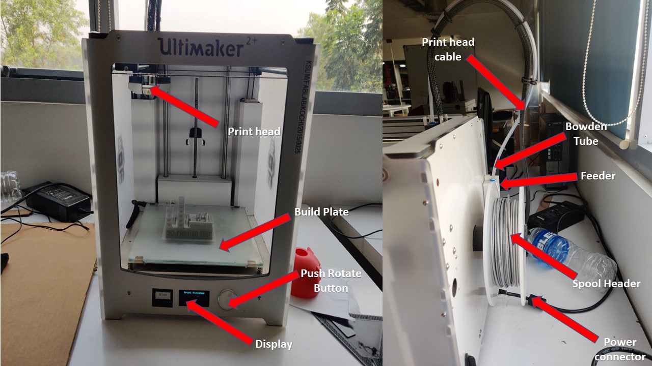
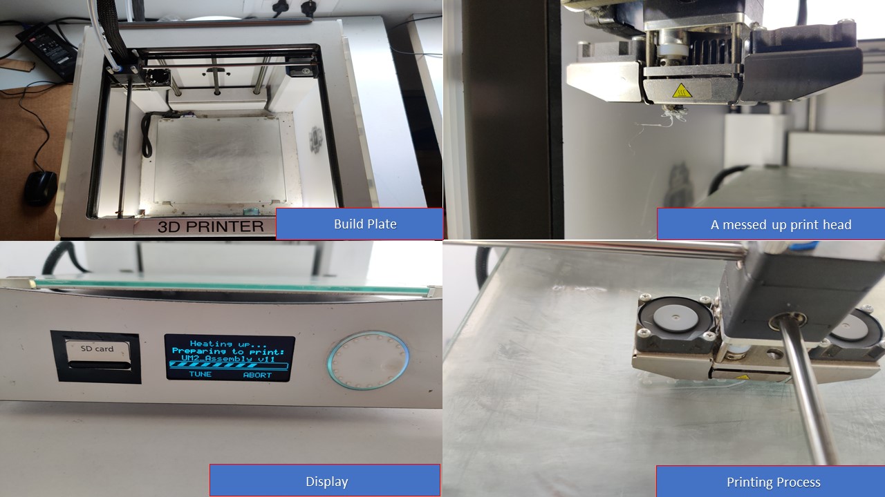
The 3D Printer in our lab is Ultimaker 2+. At the front there is a SD card slot, a small screen and a rotatable button for navigation and selection. The power switch is placed at the back, and also the filament roll is mounted at the back. The extruder can move along the X-axis & Y-axis and the bed moves in the Z-axis. This machine has an option for mounting a second extruder. It has got a layer resolution upto 20 microns. The specifications of the printer is as follows:
| Build volume | 22.3cm x 22.3cm x 30.5cm |
| Print speed | 30mm/s - 300mm/s |
| Travel speed | 30mm/s - 350mm/s |
| Filament diameter | 2.85mm |
| Nozzle diameter | 0.4mm |
| Nozzle temperature | 180-260 degree celcius |
| Bed temperature | 50-100 degree celcius |
| Printer Technology | Fused Filament Fabrication (FFF) |
Setting up Ultimaker 2+
- First you need to load the sd card containing the g code file exported from Cura.
- Then you need to choose the material by going into material, choose the material and replace if necessary
- Then if required you need to go to maintainace and level the build plate to ensure that the surface is flat
- Now, you need to go to go to print, then select the folder. Then you need to proceed for printing
Some mistakes to avoid before, during & after 3D Printing using Ultimaker 2+
- Never ever forget to level the build plate before the print otherwise you could end up in a model different from what you had made
- If you feel that the first layer didn't stick well with the place/ if nozzle carries yoru first layer along with it then it's the best time to abord the print to avoid material wastage
- Always check the dimensions of your model before print and do keep an eye on the print time and material
- Don't ever rely on the time shown in display during print as it may change a lot and ruin your expectations
- Be patient during the printing process, the intial motion of the header may change from your expectations so keep your fingers crossed
- Do keep an eye on material used and what's left so that you won't damage your print
- Don't remove SD card in between the print as the mistake may cause you a fortune
- Finally, if you don't know to troubleshoot then don't do it. Ask for help from the instructors
Some other 3D Printers available in Superfablab Kerala
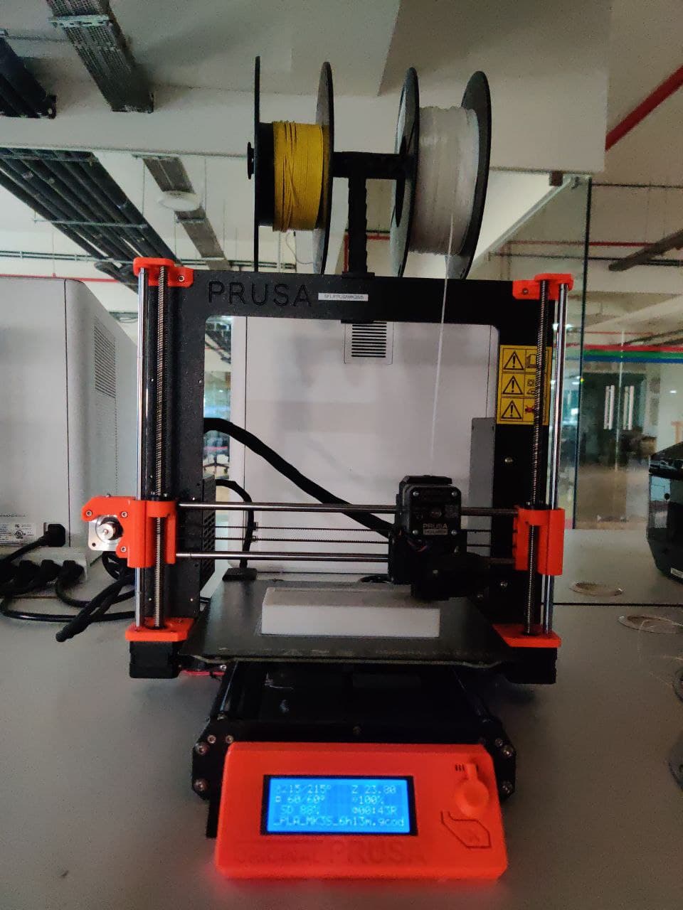
Prusa I3 MK3S
This is once of the most awarded and has the best value for money 3D printers available in the market. One of the advantages of Prusa is its self-calibration and the Removable Magnetic Bed. There are two types of base, the Smooth PEI and the Textured PEI. This also helps us with the lower finish if we want it smooth or textured, also for the adhesion of the materials. When you change the base in the Prusa I3 MK3S we must recalibrate the first layer. These values are different from each printer and sometimes influence even plastics. For the Smooth PEI base only PLA or CorkFill can be used and the value would be - 0.510 for PLA and -0.505 for CorkFill. For PETG or FilaFlex only the Textured PEI base can be used, since it has so much grip the smooth that can be damaged when the piece is removed.
| Type | Fused Depositon Modeling (FDM) |
| Nozzle Diameter | 0.4mm |
| Layer Thickness | 0.05mm -> 0.35mm |
| Materials | PLA, ABS, PETG, ASA, FilaFlex, Wood Filament |
| Build volume | 250 x 210 x 210 mm |
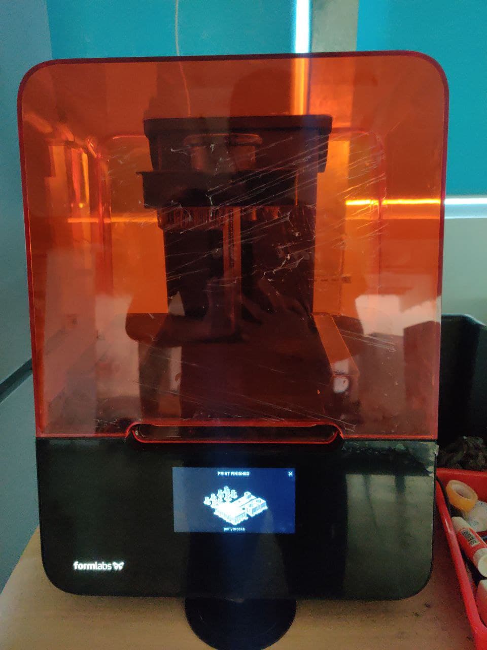
Formlabs Form 3
The Form 3 from Formlabs is a high-end Stereolithographic (SLA) printer that uses a laser to zap liquid resin into solid form. It's a sophisticated printer that can produce excellent quality prints with little maintenance or tweaking, making it a great pick for those who want to do a lot of printing without hassle. The main issue with this printer is it's price since it starts from $3500 but it's known to produce very high quality prints. The Form 3's laser and optics are found under the resin tank, located in a sealed package called the Light Processing Unit (LPU). This, Formlabs claims, makes the printer more reliable as dust can't get in to block the path of the laser. It also makes the LPU easier to replace, as the whole unit can be easily removed and replaced by the user. The Form 3 includes an excellent touch screen that allows you to control the printer directly, accessing all of the features and stopping or starting prints. Most users will turn to the PreForm software and the online printing dashboard to operate the Form 3, though. PreForm is the software that prepares your print, loading a 3D model (standard .stl and Wavefront .obj formats are supported) and slicing the model for printing.
| Type | Low Force Stereolithography |
| Laser Power | One 250 mW laser |
| Layer Thickness | 25 – 300 microns |
| Build Volume (W x D x H) | 14.5 × 14.5 × 18.5 cm |
| Laser Spot Size | 85 microns |
Design and 3D print an object that could not be made subtractively.
The idea seems complex at first but it simply means that you need to design something that can only be manufactured using 3D printing. So coming to how a 3D printer works: A 3D printer is like any CNC machine and it runs on G code, which is generated from a 3D model by software. In our case we used Cura for slicing and converting the 3D model into G code, which the machines understand. What happens is the that the software slices the 3d Model into a series of layers and then convert this data into a series of G code instructions that the machine can follow. In 3D printing, we are not limited by the constrains posed in normal manufacturing techniques, hence we can cheat architecture into impossible shapes. Our assignment was to make something which cannot be made any other way. The reason you cannot make my model subtractively is because, it is one structure locked inside another one. This would be very difficult to make using any regular milling or casting operation, but can be done with ease in a 3D printer.
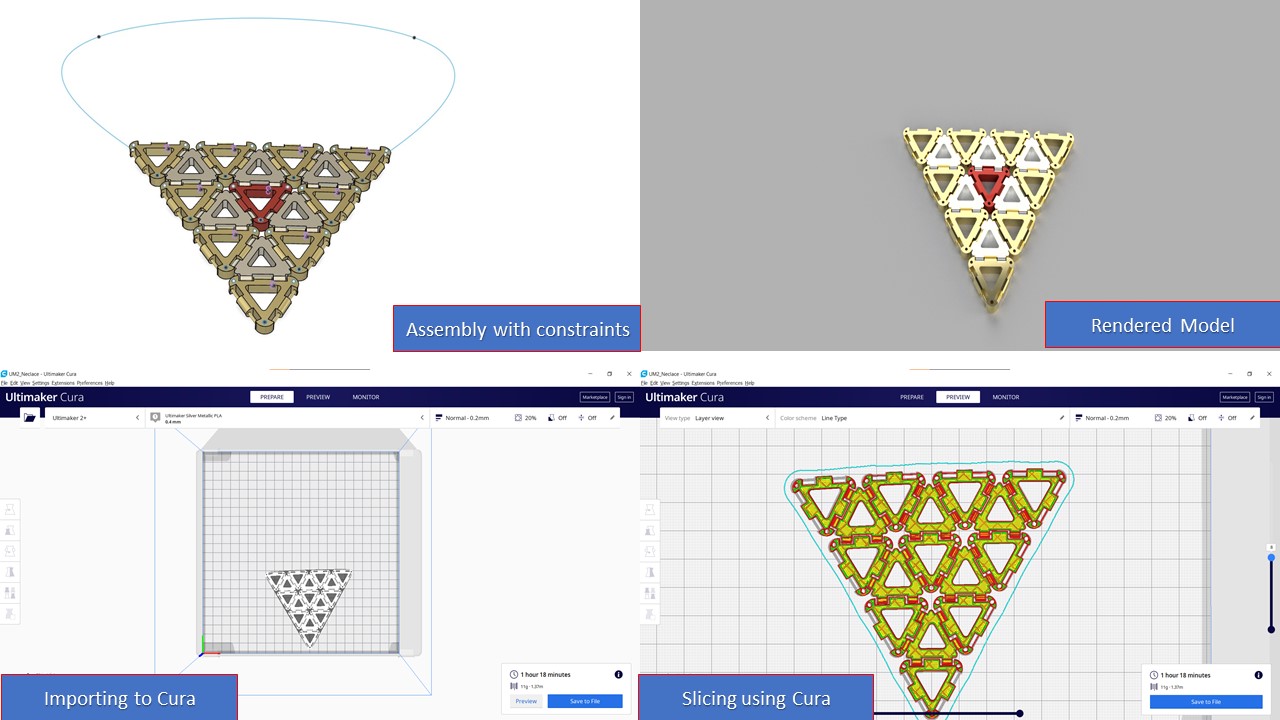
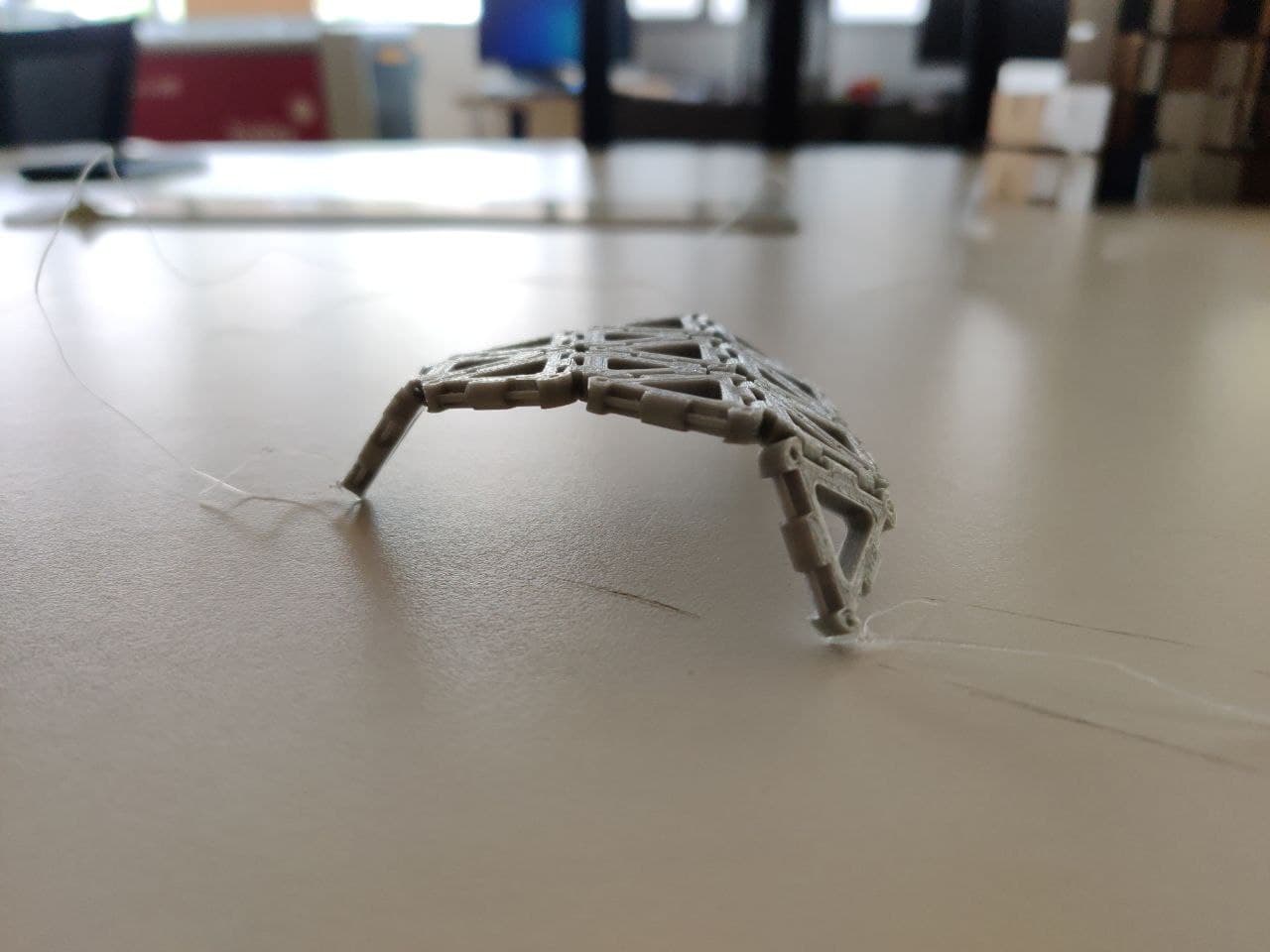
Since I have knowledge in Fusion 360, I had used it to design the model for this week's assignment. The idea is to design a parametric kit similar to what I had done in Laser cutting assignment but the cool part is that instead of assembling the model after printing, I have to export the assembled model with hinges that could potentially be used as a single component without supports. My crazy brain made my hands to design a kinematic neclace that could be can be folded as well as provides a simple aesthetic appeal to the user. I didn't want to waste material as well as time of my classmates so my approach was to simply print a test hinge and test it's capability after that I could print the whole necklace. So, these were the steps involved in making the kinematic necklace which I was first introduced from this kinematics dress made by nervous systems.
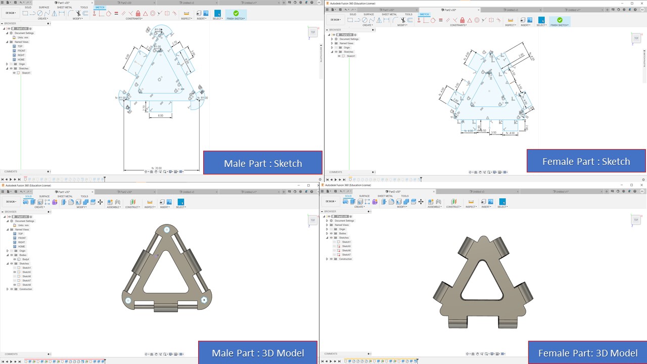
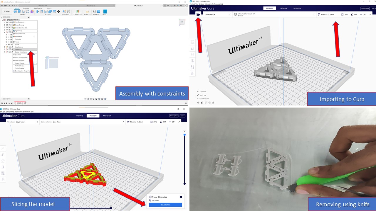
The first step is to design the male and the female parts using Fusion 360. I used parametric design to make the process easier in the longer run. The clearance and the minimum thickness the printer can print was derived from the data obtained from the group assignment. After sketching, the next step was to extrude the model and the height was chosen appropriately. Once the component is made, the male & the female part was imported to the assembly plane and using joint feature with revolve constraint the assembly was completed. Please do keep an eye on clearance as the hinge may become stuck after the print. The next step is to import the assembly to .stl file by going into the browser and right clicking the assembly to save as stl. Now, it's time to import the model into Cura (the slicer), Once imported you need to place the model appropriately and can resize the model if necessary. Please check the material type, nozzle size, infill, layer height for the print before slicing. I had chose 0.2mm layer height, 20% infill, no supports and no adhesion with grid infill for the trial print. After slicing I can check the time required for the print and it was below around 1.5 hrs. Then you need to click the Save to file option to save the .stl file as Gcode in SD Card. Now as mentioned earlier you need to insert SD card in the printer and start the print. Once the print is over, use a knife to remove the model from the build plate. For the test print, I had made a keychain which contains the hinge mechanism. I made this to find the mistakes that I made inorder to refine the model before the final print
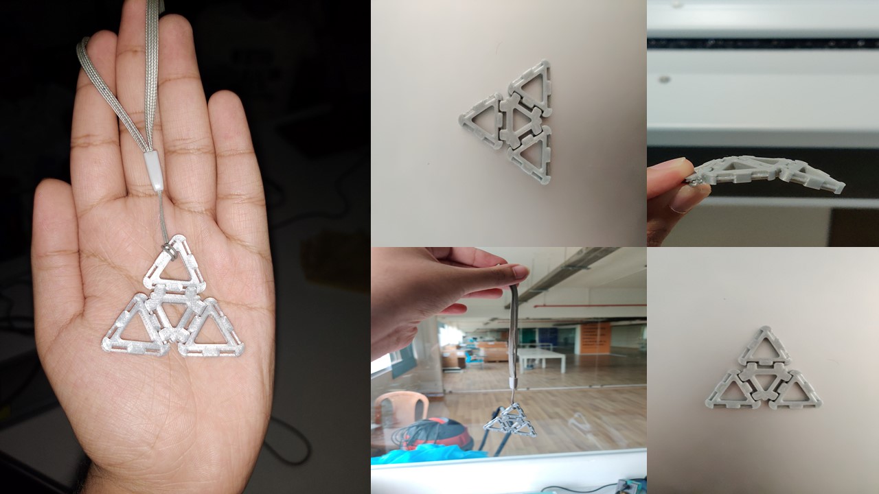
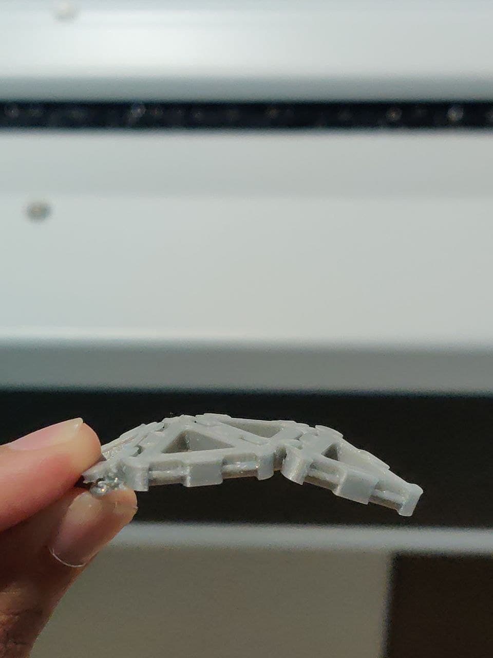
Clearance Added
I added a clearance of 1 mm so that parts could move relative to each other & not frozen in place. Since the 3D printer is accurate, the hinge worked successfully.
Lessons learned
- I had provided a fillet in the sketch which had made affected the fillet after the solid has been made and had interrupted the free motion of hinge. So only provide fillet after extrude operation.
- Check the size of the model before importing to Cura, otherwise the resizing tool may change the dimensions which won't match with your expectations
- Keep an eye on time and material left inorder to prevent your prit getting damaged.
3D Printing the Kinematic necklace
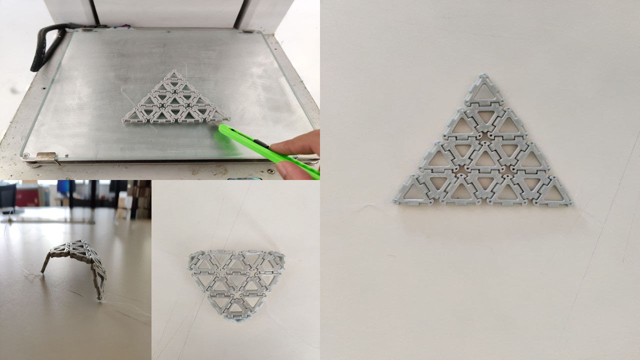
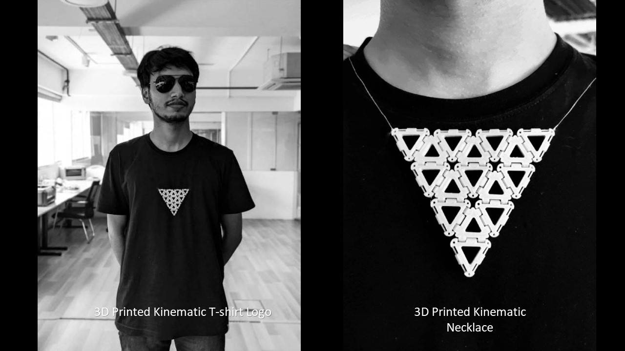
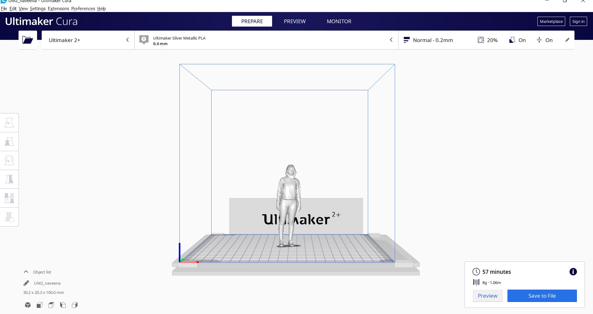
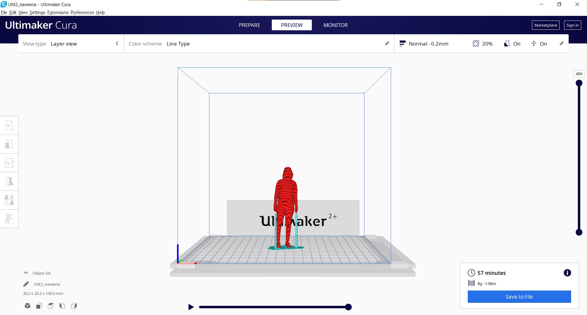
I learned from the mistakes I made during the test print which include the errors in adding fillet. Following the previous steps, I had made an assembly of a necklace which is capable of folding. Then I rendered the model using Fusion 360 render tool and exported the image as .stl. The stl file was imported in Cura, applied the required paramateres, sliced and exported the file as Gcode to SD card. After the print, I had removed the print from the bed and it met my expectations. With the help of my classmate Saheen, he tried out the necklace and for fun I also tried to make the iron man arc reactor t-shirt inspired from Tony Stark's costume from Avengers End Game.
Group assignment: Design Rules of 3D Printer
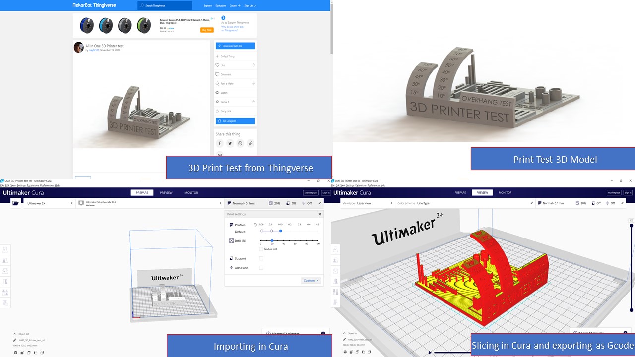
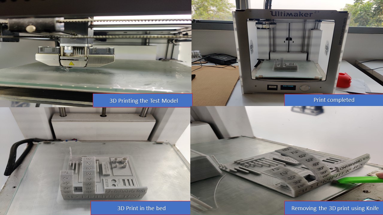
Different 3D printing processes have different capabilities and different design restrictions. In this assignment we will talk about key design considerations that apply to all 3D printing processes. Understanding the 3D printer's limitation is important because this will reflect on the actual print quality of our prototype. Inorder to test the capability, we have downloaded a test print model from thingiverse and is shown below with the test parameters.
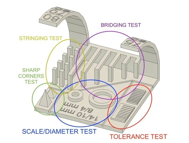
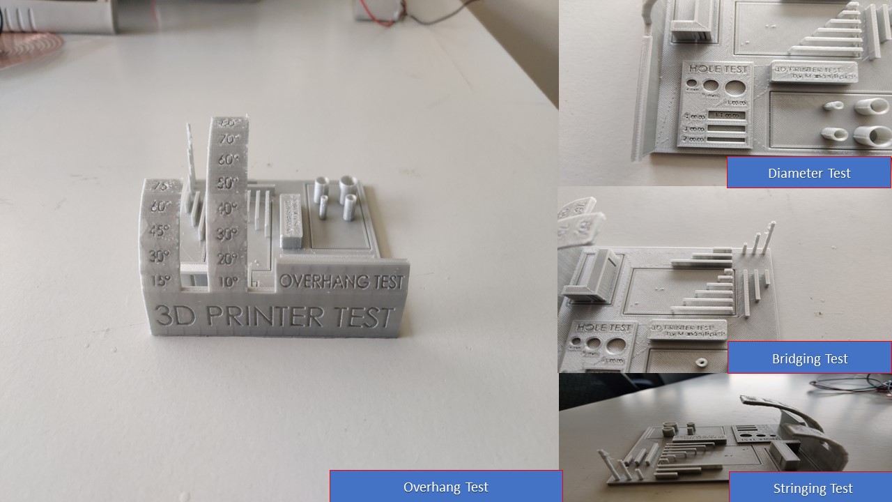
It allowed us to make different tests in one shot; an overhang test, bridging test, stringing test,sharp-corner test, tolerance test, and scale test. Repeating the above process, we have downloaded the model, imported it into Cura, sliced the model with no supports and no adhesion. The layer height was chosen 0.15mm with 20% infill and the sliced model was exported as Gcode. The SD card with Gcode was inserted into the 3D Printer and printed. After printing, the test model was removed using knife from build plate and various parameters were measured with naked eye as well as using a vernier calliper.
The following terms explains about various tests performed and checks whether the printer met our expectations.
- The Overhang :
- The Bridging test:
- Wall test:
- Cylinder test:
- Hole test:
- Rectangular Hole Test:
This test allows you to know to which angle our printer can print without the need of a support ! Usually, overhangs up to 45° can still be printed without loss of quality. That’s because any layer in a 45° overhang is mostly supported by the layer beneath. In other words, each new layer has enough support to remain intact and to make printing possible. However, anything past 45 ° approaches the horizontal and becomes difficult to print. Such overhangs are prone to curling, sagging, delamination, or collapsing. Exceeding 45 degrees means every new layer has less of the previous layer to bond with. This translates to a poor quality print with droopy filament strands.
What we got: starting from 45° the quality of the printing started to get so saggy
Bridging is the printer's ability to print a layer between gaps in lower layers without support, essentially printing over thin air, creating a "bridge". It is very important that your printer can properly bridge, because many prints require some bridging.
What we got: the quality of the bridges looked perfect except the last one.
This thing allows you to test the thickness of the wall along X and Y axis inorde to check the accuracy
What we got: For X wall we got 1.8mm instead for 2mm and 1.8mm for Y wall instead of 2mm.
This thing allows you to test the accuracy of your printing process and to determine the optimal clearance between moving parts (e.g. hinges).
What we got: We got 0.3 mm as wall diameter, for 4mm outer dia cylinder we got 3.6mm, 6mm outer dia cylinder we got 5.6mm, For 8mm cylinder we got 7.6mm as outer dia and for 10mm we got 9.6mm as outer diameter
To see how closely a final 3D printed hole measures can be, compared to its digital model. The values of the holes were 4,6 & 8mm.
What we got: For the 4mm hole we got the value as 3.95 which is almost accurate. For 6 mm hole the value was 5.95mm and finally for 8mm we got 7.95mm. The X axis values were found more accurate than Y Axis.
To see how closely a final 3D printed rectangle measures can be, compared to its digital model. The values of the holes were 4*14, 3*14 & 2*14mm.
What we got: For the 4*14 mm rectangle we got values as 4.08*13.85. for 3*14 rectangle we got 3.08*13.85 and finally for 2*14mm rectangle we got 2.08*13.85 as value
3D Scanning
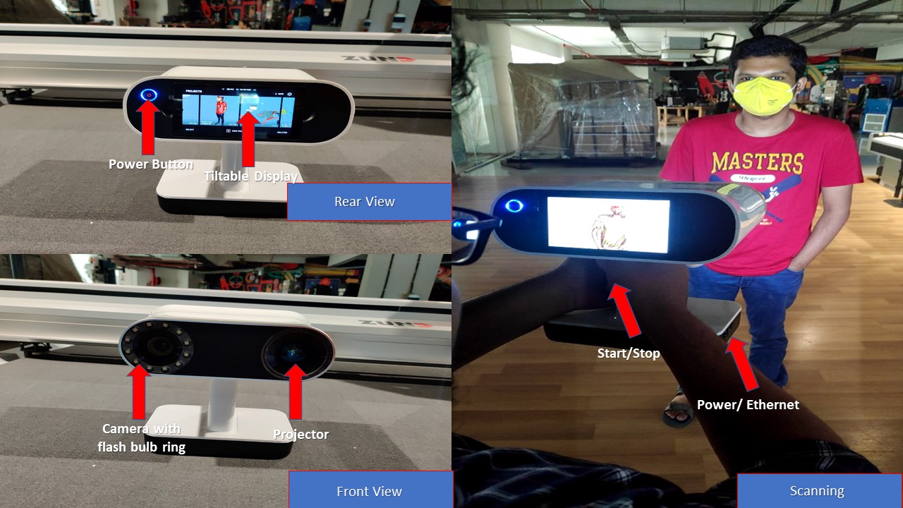
Artec Leo
Leo is an ergonomic, handheld 3D color scanner with automatic, onboard processing, released in 2018. The Leo features a touch screen panel so users can watch in real-time as a 3D replica of the scanned object comes to life. By rotating and zooming the model, the user can see if any areas were missed, thus allowing full coverage in one scan. With a working distance of 0.35 – 1.2 m, Leo is a professional, high-speed scanner, designed for capturing everything from small parts all the way up to large areas such as heavy machinery. It has an angular field of view of 38.5 × 23° and a 160,000 cm3 volume capture zone. Data acquisition speed is up to 3 million points/second. No need for target markers, and Leo can operate effectively in broad daylight or complete darkness, and everything in between. Fully mobile and entirely wireless, no cables needed. SSD memory cards make possible unlimited captures. Built on the NVIDIA® Jetson™ platform, with a TX1 Quad-core ARM® Cortex-A57 MPCore CPU, NVIDIA Maxwell™ 1 TFLOPS GPU with 256 NVIDIA® CUDA® Cores; a built-in 9 DoF inertial system, with accelerometer, gyro and compass, so Leo always understands its physical position and surroundings.
| Working distance | 0.35 – 1.2 m |
| Weight | 2.6 kg / 5.7 lb |
| Dim. H × D × W | 231 × 162 × 230 mm |
| CAD formats | STEP, IGES, X_T |
| Multi core processing | NVIDIA® Jetson™ TX1 Quad-core ARM® Cortex®-A57 MPCore Processor NVIDIA Maxwell™ 1 TFLOPS GPU with 256 NVIDIA® CUDA® Core |
| 3D light source | VCSEL |
| 2D light source | White 12 LED array |
Due to low accuracy of Xbox Kinect Scanner I went to Artec Leo. The Artec Leo is one of the most expensive as well as accurate 3D scanners available in the market. It has one physical on/off button and an interactive touch screen. The following are the steps involved in 3D scanning using Artec Leo:
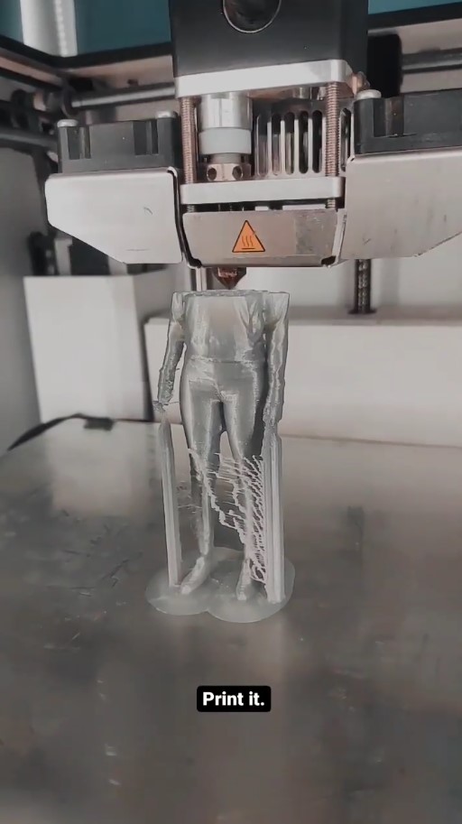
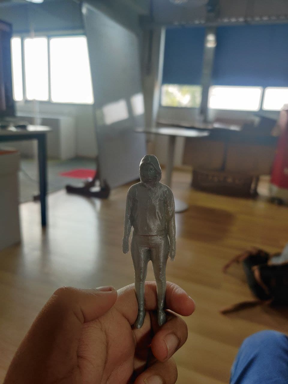
The first step is to turn on the scanner and click new project to scan the object. I tried to scan myself with the help of my instructor Mr. Jogin and it was a roller coster ride. First of all the my hairs reflected the light which affected the scanning of my head. It took around 3 minutes to scan me and it was a bit tricky to be honest. After scanning, I had exported the from the scanner via Wifi to Artec Studio 14. By manipulating various parameters we get the final model. Due to errors in software I couldn't complete the post processsing so I am adding the images of post processing steps conduct on my friend's model. I will update once the software issues ae fixed. After post processing the model is exported as .stl and is imported to Cura. After slicing, the model is resized and printed using 3D Printer and the result was obtained as expected.
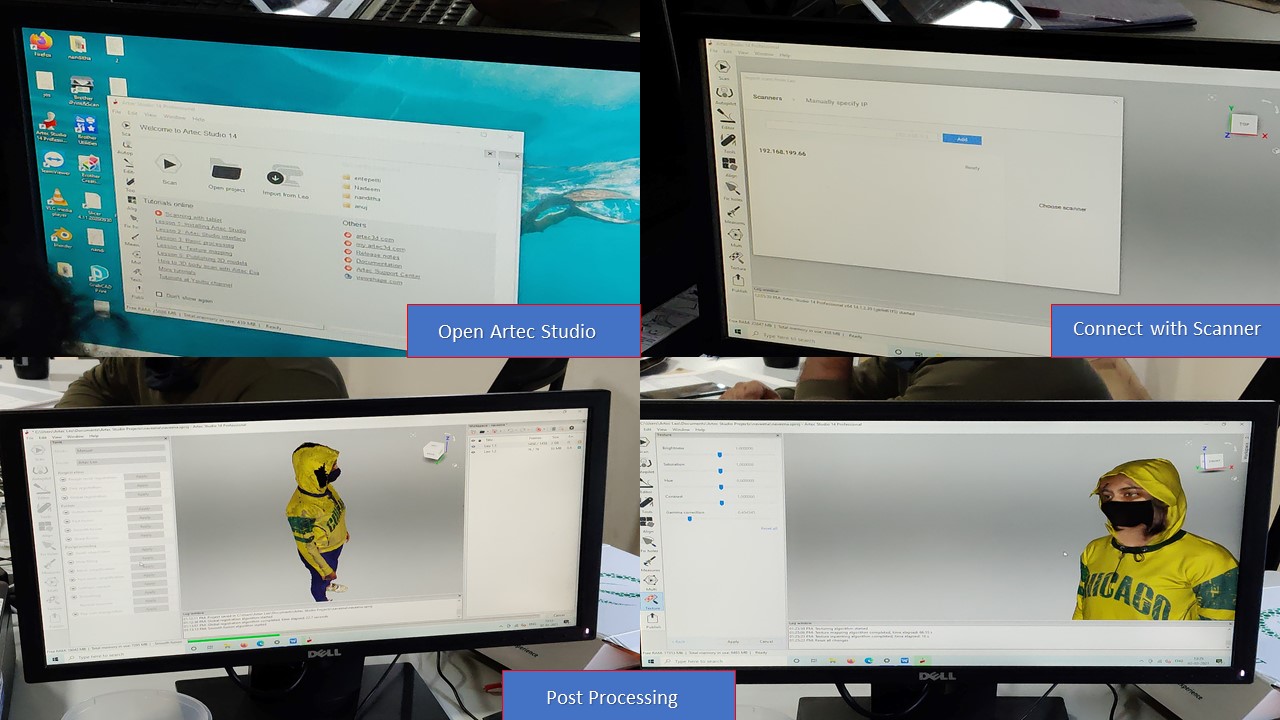
The file size was huge and it was processed in the lab PC since the propreitory software was installed in that PC Only, and it was in wrl format. The file was then exported as STL file and was fed into Cura.
3D Scanning using Qlone 3D by Eyeclue Vision Technologies
Qlone, the all-in-one tool for 3D scanning & AR. We have made it easy and fast to scan real objects, using your phone's camera, and seamlessly export the result to many platforms, 3D file formats and 3D printers… all on your Android device. A perfect tool for AR/VR (Augmented Reality) content creation, 3D Printing, STEM Education, eCommerce showcase and many other uses. Scanning real objects has never been easier. Print the included AR mat, place your object in the middle of the mat and let the Augmented Reality dome guide you through the scanning process. Scan the object from two different angles and it will be auto merged for better and more complete 3D results.
Here are the steps involved in the process:
- First you need to print the mat in a flat A4 sheet paper and you need to keep the object to be scanned inside the markings
- The next step is to open the Qlone app and click scan button. Now follow the steps to complete the hemisphere.
- Once scanned, you can export the model online, GIF or video.
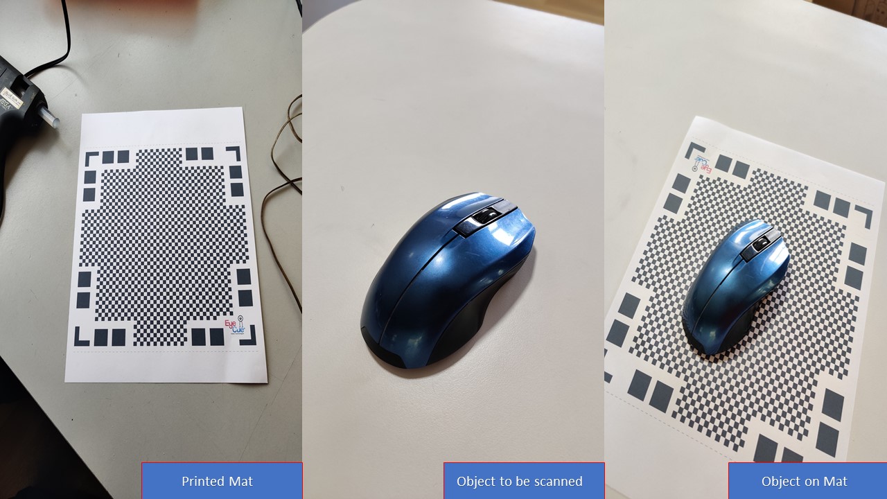
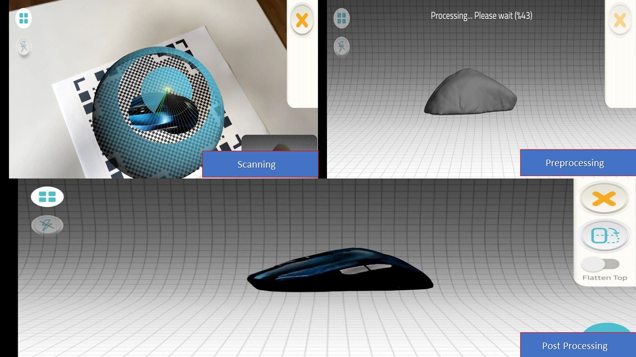
For the 3D scanned mouse, the software automatically did the postprocessing and was directly exported to STL format from application.